Privacy statement: Your privacy is very important to Us. Our company promises not to disclose your personal information to any external company with out your explicit permission.
1 Introduction
Ball-end milling cutters are important tools for CNC machining complex surfaces (especially free-form surfaces), and the market demand is large. Due to the complicated blade shape of the ball-end milling cutter, most of the machining of the ball-end milling cutter at home and abroad needs to be realized on the multi-axis linkage CNC machine tool. Because the equipment is expensive (up to millions of dollars), the single-piece machining cost of the tool is higher. high. In order to reduce the cost of tool processing, the author began to study the non-CNC machining method of ball-end milling cutters in 1991, and together with the co-investigators, proposed the mathematical model of the rake face and the flank face of the ball-end milling cutter, and discussed the hard The related machining model of the ball-end milling cutter and the sequence production of the ball-end milling cutter. In the in-depth research and development of the ball-end milling cutter, in order to solve the complicated problem of the flank grinding mechanism in the original machining scheme, the plane curve master is used instead of the space curve master to process and succeed, further reducing the milling. Knife processing costs.
In order to make the general concept of the principle and method of non-CNC machining of ball-end milling cutters, this paper gives a summary introduction to the processing principles and related main mathematical models for final product formation.
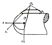
 Figure 1 Principle of rake face processing |
In order to establish the main mathematical model of the rake face machining, the right-handed rectangular coordinate system s=[O;x,y,z] and s 1 =[O 1 ;x 1 ,y 1 , respectively, fixed on the workpiece and the grinding wheel are selected. z 1 ] (see Figure 1), where y and y1 are parallel and pointing upwards. If the radius of the big end of the grinding wheel is R 2 , the half apex angle of the cone wheel is g, the distance from the big end of the grinding wheel to O 1 is p, and the angle between the z and z 1 axes is f, then when the radius of the ball head is R, The transformation from the coordinate system s 1 to the coordinate system s is
| r ={x,y,z}={x 1 cosf+z 1 sinf-psinf,y 1 +R 2 ,x 1 sinf+z 1 cosf+R-pcosf} | (1) |
| r 1 ={x 1 ,y 1 ,z 1 }={ucosv,usinv,p+(R 2 -u)cotg} | (2) |
 | (3) |
| x *2 +y *2 +z *2 =R 2 | (4) |
| X=[X 1 ,X 2 ,X 3 ]=[p,q,R 2 ] | (5) |
 Figure 2 Principle of flank processing |
| r 2 ={x 2 ,y 2 ,z 2 } | (6) |
 ,
,  ,
,  }, the cylindrical grinding wheel radius is R 1 , then there is
  | (7) |
 ,
,  ,
,  }, then the P-point trajectory equation is
 | r P =r 2 +R 1 t | (8) |
| r p = r p 0 +l( r p - r p 0 )/( r p - r p 0 ) | (9) |
Due to space limitations, this article will not list the specific expressions of the above-mentioned main mathematical models. It should be pointed out that the mathematical model given in this section is more concise than the corresponding mathematical model in other literatures, and the corresponding profile curve is easier to manufacture and easy to replace (to meet the needs of processing different specifications of the tool), so it has obvious superiority. Sex. When machining the flank, there is a problem of optimizing the selection of y 0 and R 1 values. The selection principle is to make the tool have a certain back angle and to ensure sufficient strength at the cutting edge. The specific treatment method is omitted here.
5 ConclusionNovember 11, 2024
Письмо этому поставщику

Privacy statement: Your privacy is very important to Us. Our company promises not to disclose your personal information to any external company with out your explicit permission.

Fill in more information so that we can get in touch with you faster
Privacy statement: Your privacy is very important to Us. Our company promises not to disclose your personal information to any external company with out your explicit permission.